Driver's Guide for openBVE and BVE
Welcome to the Railsimroutes.net Driver's Guide, a resource to help beginners and new BVE users learn the basics about driving the trains used by the routes developed here at Railsimroutes.net. The Railsimroutes.net Driver's Guide is a 'work in progress', and will be expanded over time, but please use the links below to learn more about the subjects already covered.
Contents
- Introduction - Simulated Signalling in openBVE ↓
- Basic Signalling Principles ↓
- Junction Signals ↓
- Approach Controlled Signals and Junctions ↓
- Banner Repeaters ↓
- Ground/Shunt Signals ↓
- Theatre Route Indicators ↓
- Signalling Safety Systems - Trackside and In-cab (AWS, TPWS, DRA, etc) ↓
- Other Cross-City Signals ↓
Introduction - Simulated Signalling in BVE
This page contains an explanation of basic UK signalling and in-cab safety systems related to signalling, which will be useful while you drive routes in BVE. This page will be expanded over time.
Thanks to Steve Green and Simon Gathercole for certain information and in-cab images used on this page.
Basic Signalling Principles
In the UK, absolute block signalling is used, and in most cases, in conjunction with multi-aspect colour light signals although some semaphore signals remain. A block is the section of line between two signals, and only one train should be allowed into a block at a time. On the Cross-City South and Watford Junction to Milton Keynes BVE routes, two of the most common signals you'll encounter are 4 aspect and 3 aspect signals. These 'multi-aspect' signals and signalling blocks are arranged as follows:
4 Aspect Signals:

3 Aspect Signals:

Recommended actions:
When you encounter green signals, you can proceed at normal linespeed, and no action is required. When you encounter a restrictive aspect, i.e. a double yellow or single yellow, then you must begin to brake so that you can stop in time for the signal which is at red. You must judge this braking distance for yourself, based on your route knowledge - i.e. you have to know where all signals are located, so you can judge how quickly or slowly you need to decelerate in order to stop at the red signal. The overriding priority is not comminting a 'SPAD', or 'Signal Passed at Danger'. You should always keep safety as the highest priority, so always ensure you're travelling at a slow enough speed to stop the train before the red signal.
Junction Signals
At junctions, signals are fitted with Junction Route Indicators or 'Feathers', to indicate which route you are about to take. Junction Route Indicators work as follows:
Taking the main line straight ahead

If you are not diverging from the main line, then the feather remains unlit, and the the signal can be treated like any other.
Taking the diverging route

If you are taking the diverging route, then the feather is illuminated, and you must proceed at the linespeed of the diverging route.
Approach Controlled Signals and Junctions
Approach controlled signals at junctions are held at red until you get close to them, at which point if the line is clear, the signal will also clear, allowing you to proceed. This is done as a means of ensuring you slow your train down in time for the junction.
How it works:

If you are taking the diverging route, then the junction signal is deliberately held at red. This, of course, causes the preceeding signals to show restrictive aspects, and this in turn ensures you slow your train down in time for the junction.

When your train approaches the junction signal, and if the line ahead is clear, the aspect will change and the feather will illuminate, allowing you to proceed through the junction.
Banner Repeaters
Banner Repeaters are used in conjunction with signals located where they can't be seen for a long enough time when approaching them, usually because the signal is situated on a sharp curve. Banner Repeaters therefore give you advanced warning of the associated main signal's aspect.

A black horizontal bar means the associated signal is showing a red aspect.

A black diagonal bar means the associated signal is showing a green or yellow aspect.
Ground/Shunt Signals
While driving Cross-City South you may notice some small signals fitted at ground level, with red/white aspects showing. These are Position Light Ground Signals, and are used to permit shunting activities within a signalling block. Ground signals work as follows:
Theatre Route Indicators
Theatre Route Indicators are (usually) fitted above a signal aspect, usually in slow speed areas or stations, and can display letters or numbers to indicate which route you will be taking, or which platform you will be entering.
A Theatre Indicator showing that you will be entering platform 8.
Signalling Safety Systems - Trackside and In-cab
Trains and most signals in the UK are typically fitted with a safety system called the 'Automatic Warning System' (or AWS), which gives different audible and visual cues within the cab to the driver, depending on the aspect shown on the signal. The AWS can also automatically apply the brakes if the driver fails to ackowledge an AWS warning. In recent years a second safety system has also seen more widespread installation on the UK rail network - the 'Train Protection and Warning System', or TPWS. TPWS is a more sophisticated safety system, which is designed to minimise 'Signals Passed at Danger' (SPADs), by automatically applying the brakes if a signal showing a red aspect is approached too fast, or if a danger signal is passed. TPWS can also be used to automatically apply the brakes if a train approaches a linespeed reduction too fast.
How the 'Automatic Warning System' (AWS) works:
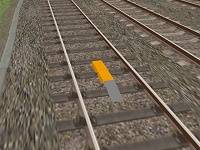 The Automatic Warning System uses electro-magnets fitted to the sleepers, called 'AWS magnets' or sometimes 'AWS ramps'. An AWS magnet is installed 200 yards before it's associated signal. The electro-magnetic field generated by the magnet is detected by AWS equipment fitted to the train (usually under the bogie).
 When a green aspect is shown on the signal, the on-train equipment will detect this through the AWS magnet, and a bell will sound in the cab on passing the AWS magnet. In this case, no further action is required by the driver. When a red or a yellow aspect is shown on the associated signal, a horn is sounded in the cab instead, and the driver must acknowledge this warning by pressing and releasing the 'AWS Reset' button in the cab. If the driver fails to do this within 3 seconds, the on-train AWS equipment will make an emergency brake application which can't be over-ridden until the train reaches a stand-still.
Note: AWS magnets may also be used in locations other than signal approaches. For example, an AWS magnet is placed before an Advanced Speed Restriction Warning Board, where the approaching linespeed is at least 60mph, and the reduction in linespeed is at least one third of the approaching linespeed.
AWS within the cab:
The AWS equipment visible in the cab consists of two components, the AWS 'sunflower' instrument, and the AWS Reset button (in ths case, the rounded polished metal button).


When you encounter a green signal, on passing the AWS magnet the in-cab AWS equipment will sound a bell or generate a digital 'bing' sound, depending on the type of train. The AWS 'sunflower' instrument will remain black, or turn black. No action is required by the driver.
When you encounter a signal showing either a red or yellow aspect, on passing the AWS magnet the in-cab AWS equipment will sound a warning horn. The AWS 'sunflower' instrument will display yellow and white marks (the 'sunflower') once you have pressed and released the AWS Reset button.
Note: You must press and release the AWS Reset button within 3 seconds, otherwise an emergency brake application will be made. If an emergency brake application occurs, you won't be able to release the brakes or silence the warning horn until the train has stopped.
If your train also has the 'Train Protection and Warning System' fitted (see below for details about TPWS), then an 'AWS Brake Demand' will be made, the TPWS Brake Demand indicator will flash red, and the train will be braked to a halt. You will then have to wait for a 60 second timeout before you can cancel the Brake Demand with the AWS Reset button, and release the brakes.
How the 'Train Protection and Warning System' (TPWS) works:
The Train Protection and Warning System comprises induction loops fitted between the sleepers, and on-train equipment with a reciever mounted beneath the bogie.

The main parts of the track mounted TPWS equipment are the 'Overspeed Sensor' (OSS) speed trap inductors, and the 'Trainstop Sensor' (TSS) speed trap inductors. Each sensor comprises an 'Arming Loop' and a 'Trigger Loop'.
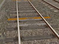
This is an example of a TPWS induction loop, in this case the 'Arming Trigger' of an 'Overspeed Sensor' (OSS) speed trap.
The inductors are only energised when the signal shows a red aspect. When the train approaches a red signal, and the on-train TPWS receiver passes the 'Arming Loop', the on-train equipment is activated, and it measures the time taken to reach the 'Trigger Loop'. If the 'Trigger Loop' is reached too quickly, then the TPWS knows the train is travelling too fast, and the system will automatically make an 'OSS Brake Demand', bringing the train to a halt. The distance between the OSS inductors varies, and the distance determines the maximum speed at which the on-train equipment makes an OSS brake demand.
The 'Trainstop Sensor' (TSS) is also energised only when a red aspect is showing. It works in a similar way to the OSS, but regardless of speed, a train passing energised TSS inductors will cause the on-train TPWS equipment to make a 'TSS Brake Demand', bringing the train to a halt.
OSS speed traps may also be used in locations other than signal approaches. For example, an OSS speed trap may be placed at the entry to a bay platform to keep approach speed in check, or at the start of a speed restriction where the approach speed is at least 60mph, and the reduction in speed is at least a third of the approach speed.
TPWS within the cab:
The TPWS equipment visible in the cab consists of a control panel with illuminated buttons and/or indicator lights:
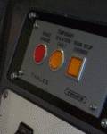 The red button is the TPWS Brake Demand indicator. This flashes red when an OSS or TSS Brake Demand is made, but can be made to glow solid red by pressing the AWS Reset button after a TPWS Brake Demand is made.
The middle yellow button/indicator is the TPWS Temporary Isolation/Fault indicator. If the TPWS is isolated or has a fault, this will illuminate yellow.
The square yellow button is the TPWS Train Stop Override button/indicator. When this is activated, the light illuminates, and the safety system is temporarily overriden to allow one TPWS equipped signal at danger to be passed without a brake demand being made, or until 20 seconds have elapsed after which TPWS returns to normal operation. You may need to activate the Train Stop Override if you received authorisation to pass a signal at danger, perhaps because of a signalling fault. This should only be done with authorisation from a signaller.
Under normal circumstances, you should never see any TPWS indicators illuminated, apart from during the startup/self-test procedure. If however you approach a red signal too fast, you will trigger an OSS Brake Demand; if you pass a signal at danger (commit a SPAD) then a TSS Brake Demand will be triggered, and if you fail to acknowledge an AWS warning with the AWS Reset button in time, an AWS Brake Demand will be triggered. When a Brake Demand is triggered, the TPWS Brake Demand indicator will flash red, emergency brakes will be applied, and the train will stop. You can't cancel the Brake Demand or release the brakes until a 60 second timeout has occured, after which the TPWS Brake Demand indicator extinguishes, and you can proceed. Normally you would proceed again only after receiving authorisation from a signaller.
Driver's Reminder Appliance (DRA):
The Driver's Reminder Appliance (DRA), is manually activated by the driver when stopped at a red signal. It simply serves as a reminder to the driver that he/she should not accelerate away without checking the signal first, for example if the train is stopped in a station with a red signal ahead. When the device is activated, it illuminates red, and the train cannot move until the device is de-activated again. The DRA should be disabled when the signal clears to a non-red aspect.

The Driver's Reminder Appliance (DRA) when not activated.

The Driver's Reminder Appliance (DRA) when activated.
Other Cross-City Signals
Here are some examples of different signals you'll encounter on the Cross-City, with some useful information.
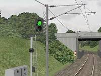
This is a Distant Signal, between Alvechurch and Barnt Green. It is a 2 aspect signal which can show either a single green, or a single yellow, and gives advanced warning of the aspect shown on it's associated home signal, i.e. the next signal along the line. If it shows a single green, this means the next signal is showing a non-red aspect. If it shows yellow, it warns you the next (home) signal is at red.
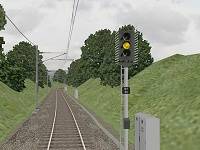
This is a 3 aspect home signal, but installed on the right hand side of the track rather than the conventional left. This is simply done to improve the visiblity of the signal.
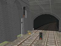
This is an ordinary 4 aspect signal outside of Birmingham New Street, but with a Theatre Indicator and a Ground Repeater. The Ground Repeater simply shows the same aspect as the associated main signal, but at ground level to aid visiblity.
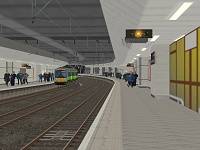
This is a 'Middle Signal', half way along the platforms at New Street. It can simply be treated as a normal 3 aspect signal, but with the aspects arranged horizontally rather than vertically. Middle Signals allow two trains to safely share the same platform, one at either side of the signal.
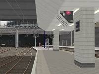
This is a single aspect signal with a built-in 'Right Away' indicator, at New Street. The single aspect is capable of showing red, yellow or green via coloured lenses, and the 'Right Away' indicator is illuminated when the train is allowed to depart - even if the signal shows a non-red aspect, you must wait for the 'Right Away' indicator to illuminate before departing.
