Driver's Guide for openBVE and BVE
Welcome to the Railsimroutes.net Driver's Guide, a resource to help beginners and new BVE users learn the basics about driving the trains used by the routes developed here at Railsimroutes.net. The Railsimroutes.net Driver's Guide is a 'work in progress', and will be expanded over time, but please use the links below to learn more about the subjects already covered.
Contents
- Introduction - Lineisde Signs ↓
- Permanent Speed Restriction (PSR) Signs ↓
- Temporary Speed Restriction (TSR) Signs ↓
- Other signs requiring driver action ↓
- Station stop signs ↓
- More Miscellaneous Signs ↓
- Other signs you may notice... ↓
▪ Introduction - Lineisde Signs
While driving BVE routes, you'll encounter many prototypical lineside signs which inform you about a wide range of things which you must act upon or take notice of, such as permanent, temporary or emergency speed restrictions, locations where the horn should be sounded, the correct stopping points at a platform, and a variety of other warnings and advisories.
Below are a selection of signs you may encounter while driving either the Cross-City South or Watford Junction to Milton Keynes Central, along with their meaning and descriptions of what actions to take when you see them.
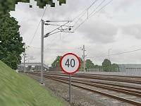
Permissible Speed Indicator (modern design)
Shows the driver the maximum permissible speed beyond this point. You should have already decelerated to the indicated speed by the time you reach this sign.
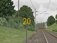
Permissible Speed Indicator (old design)
Shows the driver the maximum permissible speed beyond this point. You should have already decelerated to the indicated speed by the time you reach this sign.
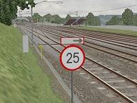
Permissible Speed Indicator with Directional Arrow (modern design)
Shows the driver the maximum permissible speed beyond this point, but the speed applies to the line diverging in the direction indicated by the arrow. You should have already decelerated to the indicated speed by the time you reach this sign, IF you are taking the diverging route in the direction of the arrow. If you are not taking the diverging route, linespeed remains unchanged. You will know which route you are taking from the signal which preceeded this sign.
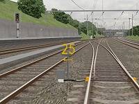
Permissible Speed Indicator with Directional Arrow (old design)
Shows the driver the maximum permissible speed beyond this point, but the speed applies to the line diverging in the direction indicated by the arrow. You should have already decelerated to the indicated speed by the time you reach this sign, IF you are taking the diverging route in the direction of the arrow. If you are not taking the diverging route, linespeed remains unchanged. You will know which route you are taking from the signal which preceeded this sign.
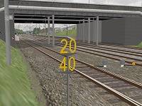
Differential Permissible Speed Indicator (old design)
Shows the driver the maximum permissible speed beyond this point. The top number applies to single axle vehicles (often freight trains), the bottom speed applies to bogied vehicles (e.g. passenger trains). You should have already decelerated to the indicated speed by the time you reach this sign.
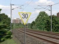
Permissible Speed Advanced Warning Indicator (modern design)
An advanced speed restriction warning board, which alerts the driver of an upcoming decrease in permissible linespeed. You should start to brake in order to slow to the line speed indicated on the warning board.
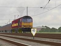
Permissible Speed Advanced Warning Indicator (modern design for limited clearance)
An advanced speed restriction warning board, which alerts the driver of an upcoming decrease in permissible linespeed. You should start to brake in order to slow to the line speed indicated on the warning board.
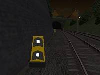
Emergency Speed Restriction Indicator
These illuminated indicators are used when emergency speed restrictions are imposed. They are positioned before any other Temporary Speed Restriction warning signs, and have an associated portable AWS magnet. These indicators are sometimes referred to as 'Daleks'!
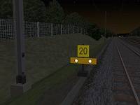
Temporary Speed Restriction Warning Board
These reflective warning boards alert the driver to an upcoming Temporary Speed Restriction (TSR) and indicate the imposed speed. These indicators also have an associated portable AWS magnet.
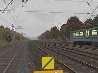
Spate Indicator
A Spate (Speed Previously Advised Terminated Early) Indicator is used when a TSR has been withdrawn ahead of schedule but the TSR boards and equipment have yet to be removed, or if the TSR boards and equipment have been installed but the TSR is no longer required. Spate Indicators are placed at TSR Warning and Speed Indicator boards, and their presence means you can disregard the TSR and maintain normal linespeed.
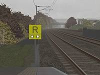
Temporary Speed Restriction Repeating Warning Board
These reflective warning boards are placed at platform ends or siding exits, and serve to remind the driver that a TSR lies ahead.
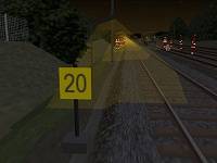
Temporary Speed Restriction Commencement Indicator
This board marks the start of the Temporary Speed Restriction, along with the speed imposed.
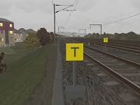
Temporary Speed Restriction Termination Indicator
This board marks the end of the Temporary Speed Restriction. Ensure the entire train has cleared this indicator before accelerating back to line speed.
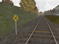
AWS Cancelling Indicator (Temporary)
Informs the driver that he/she should disregard the AWS warning just received, because the AWS indication only applies to trains travelling in the opposite direction on a single track or bi-directional line.
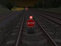
Possession Limit Sign
Indicates the limit of an engineering possession - no vehicle should pass this board without authorisation.
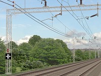
Neutral Section Warning Board
A white on black warning board which warns the driver of an upcoming neutral section, which is a short isolated section of overhead wire designed to seperate different phases of the AC supply. This board is placed 1 mile before the neutral section itself, and you should ensure that by the time you reach the neutral section, power is cut from the traction motors - this is necessary to reduce the risk of arcing at the neutral section itself, as well as to reduce wear and tear on electrical equipment.
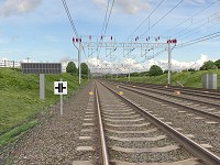
Neutral Section Commencement Board
A white warning board placed immediately before a neutral section, which is a short isolated section of overhead wire designed to seperate different phases of the AC supply. You should have cut power to the traction motors by the time you reach the neutral section; if you fail to do so, then sleeper mounted Automatic Power Control (APC) magnets will cut power and re-apply power automatically. This is necessary to prevent the pantograph drawing an arc between the two isolated phases of the power supply.
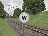
Whistle Board (modern design)
Tells the driver to sound the horn at this location. These signs are often placed ahead of foot crossings.
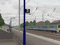
3 Car Stop Point
Indicates where a driver with a 3 car train should stop.
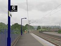
6 Car Stop Point
Indicates where a driver with a 6 car train should stop.
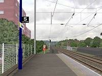
'S' Car Stop Point
Indicates where all drivers should stop, regardless of train length - used instead of Car Stop Point signs which denote specific train lengths.
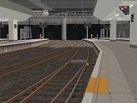
Stop Point
A section of platform edging painted orange, this marker indicates where all drivers should stop - used at either end of the platforms at Birmingham New Street.
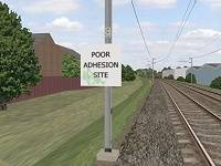
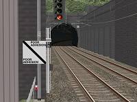
Poor Adhesion Site (Start)
Informs the driver he/she is entering a section of line where poor rail adhesion may be encountered. There may be an increased risk of wheelslip beyond this point, perhaps because of increased numbers of trees next to the line, hence a greater possibility of falling leaves causing problems.
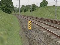
Poor Adhesion Site (End)
Informs the driver he/she is leaving a section of line where poor rail adhesion may be encountered.
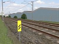
Sandite Marker - Advanced Warning
Gives the driver of a 'Sandite Train' advanced warning of an upcoming sandite application area. Sandite is a mixture applied to the rails by Sandite trains, to improve rail adhesion and decrease the risk of wheelslip.
Sandite Marker - Begin Sandite Application
Denotes the location where sandite application should begin. Does not apply to non-sandite trains.
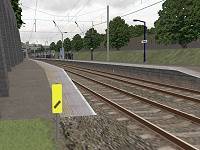
Sandite Marker - Cease Sandite Application
Denotes the location where sandite application should cease. Does not apply to non-sandite trains.
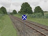
AWS Cancelling Indicator (Permanently Installed)
Informs the driver that he/she should disregard the AWS warning just received, perhaps because the AWS indication only applies to trains travelling in the opposite direction on a single track line.
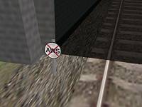
AWS Gap Commencement
Indicates that no AWS equipment is installed beyond this point.
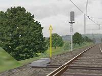
Spring Catch Points Sign (old design)
Indicates the presence of spring mounted catch points. Catch points are often installed on sidings or loops, and are used to derail runaway rail vehicles running in the wrong direction - perhaps because a vehicle uncoupled on an incline and began rolling backwards. By derailing the vehicle(s) they are prevented from fouling the main line.
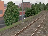
Gradient Sign
Indicates a change in gradient.
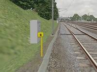
Mile Post
Indicates the current mileage from a fixed reference point.
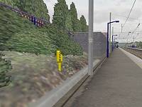
Quarter Mile Post
Indicates quarters of a mile.
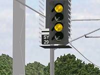
Automatic Signal/ID Plate
These signs identify the signal, and indicate the signal is automatic, i.e. the aspect it displays is dependant on the aspect shown on the next signal, unless a train is occupying the signalling block after this signal, in which case the signal reverts to red.
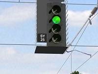
Controlled Signal/ID Plate
These signs identify the signal, and indicate the signal is controlled, i.e. the signal is under direct control from the signal box. Controlled signals are often used to protect junctions.
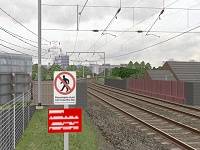
No Unauthorised Access / Passengers Must Not Pass This Point
These signs are fitted at the ends of platforms and warn passengers not to pass the sign, cross the line or otherwise trespass on to the railway.
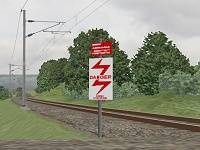
Danger - High Voltage
Warns of the presence of overhead live wires energised at 25,000 volts.
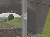
Overhead Line Equipment (OHLE) Mast ID Plate
Each mast has it's own identification plate to assist maintenance engineers.
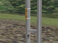
Designated Earthing Point (DEP)
Indicates that this OHLE support is a Designated Earthing Point, which is fitted with small attachments to allow earthing jumpers to be connected between them and the catenary wire when the OHLE is de-energised, thereby earthing the wires and removing any residual current.
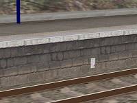
Track Position Indicator
A plate fitted to the platform side, with a sliding scale which indicates the railhead height, along with other data detailing track position. Used when the track is re-tamped, to ensure the track is in the correct position in relation to the platform.
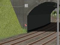
Limited Clearance Sign
This small red and white sign is attached to certain lineside structures, and warns that there are no safe places to stand between the structure and the side of the line the sign is situated.
